Author: Lê Thị Kiều Nga
Email: [email protected]
Description: Water level control model is control by S7 - 1200. The model serves for PCS control course. The model is controlled and monitored by TIA Portal Software. The parameters of the controller are adjusted by the PID algorithm. This model helps learners understand the basic control processes in the PCS system..
Specification:
- Mechanical components: 2 reservoirs, pressure reservoir, plug-in tube system, mounting frame, profile plate
- Sensors: 2 capacitive sensors, 2 float switches, flow sensor, pressure sensor.
- Actuators: pump, proportional directional control valve, ball valve with pneumatic process actuator, heating
- Electrical components: I/O connection board with measuring transducer, motor controller, I/O terminal, SysLink, 8I/8O, analogue terminal, SysLink, 15-pin
Working: Using a corresponding controller, the level and flow rate controlled system can be set up as a cascade control system.
The design of the sensors and valve actuators allows the use of both continuous (e.g. P, I, PI, PID) and discontinuous controllers (e.g. two-point controllers) in testing. The pumps can be controlled using either direct actuation or speed adjustment.
With the flow rate and pressure controlled systems, the manipulated variable of the controller can also be used to operate a proportional directional control valve. A two-way ball valve with a pneumatic process actuator is installed in the return between the elevated tank and the lower reservoir. The two-way ball valve can be used to simulate a "load" for disturbance variable compensation in the level controlled system.
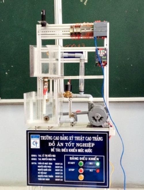
Figure 3. Water tank control model
Reference:
[1] Nguyễn Thị Phương Hà – Huỳnh Thái Hoàng, Lý thuyết điều khiển tự động, NXB Đại học Quốc Gia TP.HCM
[2] Richard C. Dorf, Robert H. Bishop, Modern control system eleventh edition
 Vietnamese
 English
